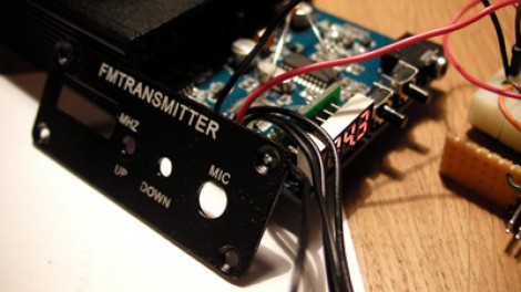
A cheap FM transmitter can be a surprisingly good embedded-systems classroom. Beneath the plastic shell and two-button interface may sit a microcontroller, a phase-locked-loop transmitter chip, a display, and capable hardware limited by firmware that forgets settings or makes tuning unnecessarily tedious.
In a well-known hobby project, an ATmega48-based transmitter had a six-pin programming header, but its program flash was locked. Instead of copying the original code, the developer stabilized the power supply, traced the circuit, erased the controller, and wrote replacement firmware. The new software added rapid frequency navigation and EEPROM-based setting retention.
Why Re-engineer FM Transmitter Firmware?
Low-cost transmitters often contain useful hardware behind minimal software. The RF chip may support digitally selected channels, stereo encoding, muting, and stable PLL tuning, while the factory interface offers slow button response, no automatic repeat, awkward frequency steps, and no memory after power loss.
Custom FM transmitter firmware can improve those behaviors without redesigning the analog section. The project also teaches power analysis, circuit tracing, AVR programming, serial-bus observation, state-machine design, EEPROM management, and controlled RF testing. It is the electronics version of planning to repaint one room and emerging three weekends later with strong opinions about plumbing.
Re-engineering Is Not Always Decompilation
Tools such as Ghidra can disassemble and decompile readable firmware images. A locked microcontroller changes the strategy: if flash cannot be read without erasing it, the engineer must study observable behavior and hardware connections instead.
The objective is not to recreate hidden code instruction by instruction. It is to understand the device well enough that the old program is no longer required.
Understanding the Original Hardware
The transmitter behind this project used an ATmega48 controller and a BH1415-family PLL FM stereo transmitter IC. The AVR handles buttons, display logic, configuration, and persistent settings. The dedicated radio chip performs the demanding analog tasks, including stereo processing, modulation, and PLL-based carrier control.
The Programming Header Was Only the Beginning
An AVR ISP connection normally exposes reset, clock, data, ground, and a power reference. With AVRDUDE, an engineer may inspect the device signature, EEPROM, fuse bytes, lock bits, and flash when permissions allow. A valid signature proves communication, not permission to read protected program memory.
Initial communication with the project board failed because its supply was unstable. A regulated source made the chip signature readable. That is a classic embedded lesson: before blaming code or tools, verify voltage, ground, reset, clocking, and signal integrity.
A Practical Firmware Re-engineering Workflow
1. Record the Factory Behavior
Before erasing anything, document startup frequency, tuning limits, channel spacing, short and long button presses, mute timing, display behavior, and power-cycle results. Take photographs and short videos. Once protected firmware is erased, those observations become the functional specification.
2. Stabilize the Power and Programming Connection
Measure the rail at the microcontroller while the display and transmitter are active. Confirm a shared ground, short ISP wiring, sensible programmer clock speed, and adequate decoupling. Marginal power can produce inconsistent signatures, failed reads, or verification errors that look like software problems.
3. Identify Components and Draw the Schematic
Read package markings and trace continuity from each controller pin. Start with power, reset, buttons, display lines, crystals, LEDs, and the transmitter chip’s data, clock, and enable signals. Even a rough schematic reveals the device’s architecture and prevents firmware assumptions from becoming expensive smoke.
4. Save Everything Still Accessible
Read the signature, fuses, lock status, EEPROM, and any permitted memory regions more than once. Compare the files to confirm repeatability. A chip erase is destructive and commonly clears flash protection, so document configuration bytes before proceeding.
5. Capture the Control Bus
If the original firmware still operates, attach a logic analyzer to the radio-control lines. Trigger a capture, press one button, and compare the resulting pattern with the transmitter datasheet. Logic analyzers can decode SPI, I2C, UART, and many related protocols, while raw timing views help with proprietary three-wire interfaces.
Look for bit order, idle polarity, latch timing, repeated frames, and fields that change with frequency. The useful question is not “Is this exactly SPI?” but “Which edge clocks data, and when does the peripheral accept the completed word?”
6. Build Minimal Test Firmware First
Start by toggling one known output, reading one button, initializing the display, and loading one fixed PLL frequency. Add features only after each layer works. A tiny test image that produces one verified carrier is more valuable than a beautiful menu attached to an uncooperative radio.
Designing Better Replacement Firmware
Use a Nonblocking State Machine
Define clear states for startup, normal tuning, rapid stepping, delayed saving, and errors. Use a periodic timer for button debouncing and long-press detection rather than blocking delays. This keeps the display and radio interface responsive.
Store frequency as an integer channel index or fixed units such as 100 kHz. Integer arithmetic is compact and avoids floating-point rounding surprises between the displayed channel and the PLL command.
Make Fast Tuning Honest
A transmitter-only board cannot identify occupied channels unless it also has receive or signal-strength hardware. A useful scan mode may simply step rapidly while the user monitors a separate radio. The firmware can pause briefly at each channel, mute during PLL updates, and provide an audible cue, but it should not claim to find clear spectrum without actual detection circuitry.
Save Settings Without Hammering EEPROM
The ATmega48 includes nonvolatile EEPROM with substantial write endurance, but firmware should not save on every frequency step. Mark the value as changed, then commit it after the user stops tuning for a few seconds.
Store a version byte, frequency value, and checksum. On startup, reject invalid data and use a safe default. Two alternating records with sequence numbers provide extra protection if power fails during a write.
Enforce Safe Frequency Limits
Keep band limits, channel spacing, and PLL conversion in one tested module. Decide explicitly whether tuning wraps at the edge or stops. Centralized frequency math prevents one button path from applying an offset that another path forgets.
Testing the New FM Transmitter Firmware
Begin with the output attenuated, shielded, or connected to suitable test equipment. Verify the carrier across several frequencies using a counter, spectrum analyzer, or calibrated receiver. Then test cold startup, long button holds, rapid direction changes, corrupt EEPROM, brownouts, power cycling, and interrupted programming.
A nearby radio confirms that something can be heard; it does not prove correct frequency, clean modulation, low spurious output, or regulatory compliance.
Respect U.S. RF Rules
In the United States, unlicensed operation in the 88–108 MHz band is permitted only under strict Part 15 limits. Section 15.239 sets a field-strength limit of 250 microvolts per meter measured at 3 meters and restricts emissions outside the allowed band. Part 15 devices may not cause harmful interference and must accept interference received. Firmware changes, antenna changes, or added RF amplification can invalidate the conditions under which a consumer product was compliant.
Treat the project as short-range experimentation. Use attenuation, shielding, dummy loads, and appropriate measurements. Never retune or amplify the device to interfere with licensed broadcasts or other radio services.
What the Project Really Teaches
A protected binary does not end an investigation; it changes the source of truth. The schematic becomes documentation, pin transitions become an interface specification, and controlled experiments reveal timing and state.
The project also proves that hardware and firmware must be debugged together. The first programming failure was electrical. Persistent settings depended on both EEPROM policy and interface design. Reliable tuning required understanding the AVR, PLL chip, power system, and RF path as one device.
Field Experience: Lessons from Projects Like This
The first practical lesson is usually humility. A developer may expect an evening of instruction decoding and instead discover that a damaged supply lead is causing every programmer error. Once target voltage is stable and the ISP clock is appropriate, supposedly mysterious failures often disappear with comic speed.
Photographs and notes are equally important. Connectors get reversed, temporary wires become permanent, and unlabeled test pads look identical the next morning. Record measured voltages, pin mappings, fuse values, and successful commands. Human memory is volatile; an engineering notebook should not be.
Tracing the board changes how the software is designed. The product stops being one mysterious “FM transmitter” and becomes smaller systems: input controls, display, microcontroller, serially controlled PLL, audio path, power network, and RF output. Those boundaries suggest clean modules. Buttons generate events, a tuner converts channel numbers into control words, storage validates EEPROM records, and the display reports state without knowing how the radio synthesizer works.
Minimal firmware also saves enormous time. A fixed-frequency test answers one important question: can the controller configure the PLL? The next build can add buttons, followed by display updates and persistence. Each version should answer one question. Oversized early builds answer many questions badly and produce bugs that arrive in groups.
EEPROM behavior provides a satisfying usability lesson. Saving every button step seems harmless during a demonstration, but delayed commits reduce writes and keep the interface responsive. Tune quickly, stop, wait for the save interval, remove power, and restart. Watching the chosen channel return is a small victory that makes the entire device feel more professional.
RF testing brings another reality check. Hearing a signal on a nearby receiver proves only that energy reached the receiver. It says little about harmonics, spurious emissions, field strength, or exact modulation. Developers quickly learn to separate “it works” from “it works cleanly and legally.” Antenna changes may affect radiated range more dramatically than firmware changes, so conservative hardware and proper measurement remain essential.
Finally, document the finished project as though someone else will maintain it. Preserve the pinout, build commands, fuse configuration, channel formula, recovery procedure, source code, and a known-good binary. Future you should not have to reverse-engineer your own reverse engineering. That would be wonderfully circular and remarkably inefficient.
Conclusion
Re-engineering some FM transmitter firmware combines power integrity, AVR programming, circuit reconstruction, serial analysis, PLL control, EEPROM reliability, and responsible RF testing in one compact project.
The decisive step is not defeating protection; it is understanding the hardware well enough to create a clean replacement. With careful observation, incremental firmware, and disciplined testing, an inexpensive transmitter can become a documented and maintainable embedded platform.