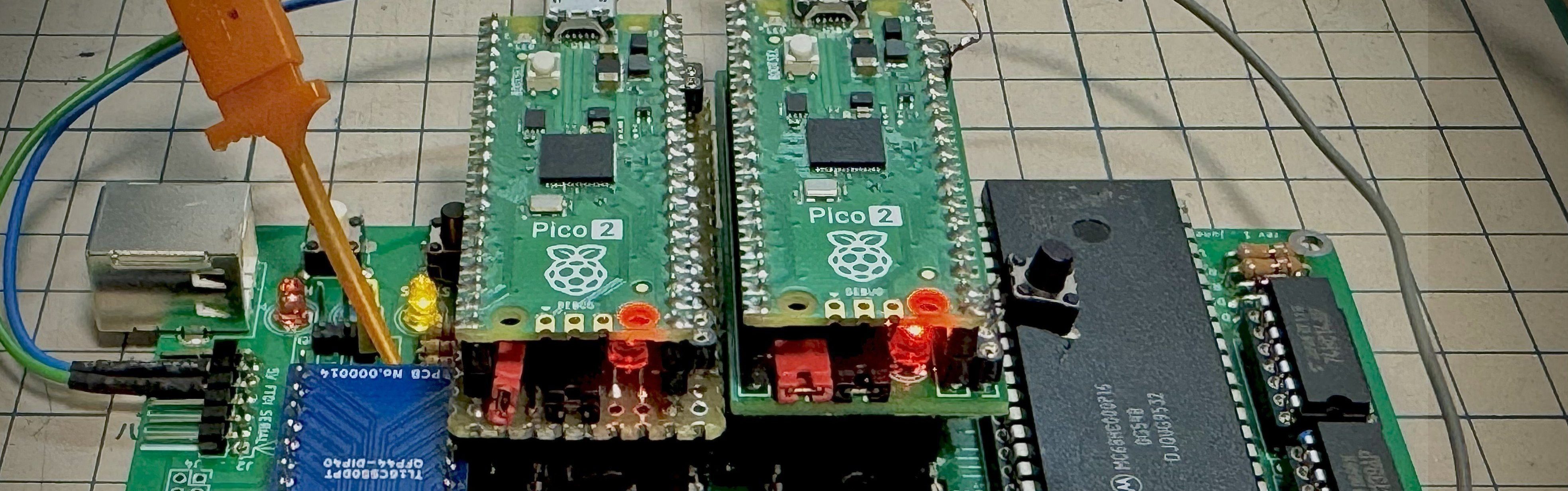
Somewhere between retrocomputing nostalgia and “wait, that tiny board can do what?” lives one of the most delightful hardware tricks of the Raspberry Pi Pico 2 era: using RP2350 PIO to emulate ROMs fast enough for classic processors running at serious speeds. The headline sounds almost suspiciously simpleemulate ROMs at 12MHz with Pico2 PIObut the idea is surprisingly elegant. Instead of asking the main Arm or RISC-V cores to babysit every bus cycle, the project leans on the Pico 2’s Programmable I/O system, a set of tiny deterministic state machines built specifically for timing-sensitive signal work.
In plain English, a Pico 2 can pretend to be an old parallel ROM chip. A vintage CPU places an address on the bus, toggles its read signals, and expects valid data to appear quickly. Traditionally, you might solve that with a real EPROM, EEPROM, flash chip, CPLD, FPGA, or a hand-soldered shrine to 1980s timing diagrams. But Pico2 PIO makes a different argument: with the right pin mapping, PIO program, and memory table, a small microcontroller board can respond like a ROM fast enough for a 10MHz Z80 or a 12MHz MC68000 system. That is not just neat. That is the kind of neat that makes a logic analyzer feel like popcorn.
What Does “ROM Emulation” Actually Mean?
ROM emulation means replacing a physical read-only memory chip with a device that behaves like one from the host computer’s point of view. The host machine does not know it is talking to a modern microcontroller. It still sees address pins, data pins, chip-enable signals, output-enable signals, and timing windows. The emulator’s job is to notice the address, fetch the matching byte or word from its own memory, and drive the data bus before the CPU loses patience.
In retrocomputing, ROM emulators are extremely useful. They let developers test firmware without repeatedly burning EPROMs. They make it easier to debug old single-board computers, CP/M machines, 68k projects, arcade boards, and custom hardware. They also reduce wear on vintage sockets, because nobody enjoys pulling a DIP chip for the 47th time while muttering at an assembler listing.
Why 12MHz Matters
A 12MHz bus is not “modern fast,” but for ROM emulation it is absolutely fast enough to be interesting. At 12MHz, a single clock period is about 83 nanoseconds. Depending on the CPU and bus design, the ROM emulator may have only a small portion of that time to decode the address and place stable data on the bus. For an MC68000-class system, the bus is wider and timing expectations can be tighter than a casual Arduino-style polling loop can handle.
That is where Pico2 PIO shines. PIO does not run a general operating system, does not get distracted by interrupts, and does not wander off to check USB. It executes small programs with deterministic timing. For this job, predictability is gold.
Why Pico 2 Is a Strong Fit for ROM Emulation
Raspberry Pi Pico 2 is built around the RP2350 microcontroller, a major step up from the original RP2040-based Pico. It offers more memory, more processing flexibility, and an expanded PIO subsystem. The board remains inexpensive and approachable, but its hardware is capable enough to handle projects that used to feel more FPGA-adjacent than microcontroller-friendly.
The key feature here is not simply the CPU speed. Yes, the RP2350 has powerful cores, but the clever part of a Pico 2 ROM emulator is that the cores are not the stars of the timing-critical show. The PIO state machines handle the bus-facing logic. The CPU can prepare tables, manage USB serial communication, load ROM images, reset the target system, or sit quietly in the corner feeling useful. The PIO state machines do the “answer the bus now, not after coffee” part.
The PIO Advantage
PIO, short for Programmable I/O, is one of Raspberry Pi’s most distinctive microcontroller features. Each PIO state machine can read pins, write pins, shift data, wait for pin states, and coordinate with FIFOs. It is tiny compared with a CPU core, but that is the point. It runs simple I/O logic with tight timing. For ROM emulation, that means it can watch address and control lines and drive output pins at the exact moment required.
Think of PIO as a very disciplined intern who only knows a few instructions but never checks social media, never misses a deadline, and never asks whether “nanosecond timing” is flexible. That discipline is precisely what a vintage CPU bus needs.
How Pico2 PIO Can Pretend to Be a ROM
A classic parallel ROM exposes address inputs and data outputs. The CPU presents an address, selects the chip, and reads the data. A Pico 2 ROM emulator must reproduce that behavior in real time. At a high level, the process looks like this:
- The vintage CPU places an address on the address bus.
- Control signals such as chip enable and output enable indicate a ROM read.
- PIO samples the relevant address and control pins.
- The emulator maps that address to a byte or word in an internal ROM image.
- PIO drives the data bus quickly enough for the CPU to read it correctly.
In practice, the exact method depends on the target CPU, the ROM size, and the bus layout. A Z80 design may use an 8-bit data bus and a familiar memory-read cycle. An MC68000 system may involve a 16-bit data bus, upper and lower data strobes, and different alignment concerns. Pico2ROMEmu-style designs typically focus on a specific ROM footprint and a practical subset of capacity, because the goal is reliable speed rather than pretending one tiny board is every memory chip ever invented.
PIO, Tables, and Timing
The hardest part is not storing the ROM image. Even modest RP2350 SRAM is large compared with many classic boot ROMs. The challenge is getting the right value onto the bus fast enough. CPU polling would introduce jitter. Interrupt latency would be risky. Cache and flash access timing could complicate things. PIO offers a cleaner path by making the bus response closer to hardware logic.
A common design approach is to arrange lookup data so that the PIO and DMA pathway can deliver bytes or words with minimal overhead. The less translation needed during a read cycle, the better. Fast ROM emulation is often won before the first read happens: by precomputing tables, aligning memory carefully, choosing pin assignments wisely, and making the runtime path as boring as possible. In electronics, “boring” is often another word for “works every time.”
Why Not Just Use the Pico 2 CPU?
The RP2350’s main cores are powerful for a microcontroller, but a vintage CPU bus does not care how impressive your benchmark chart looks. It cares whether data appears before the timing window closes. A normal C loop can be fast, but it is not always deterministic enough. Interrupts, compiler decisions, memory placement, and peripheral contention can create tiny delays. Tiny delays are where ROM emulators go to become troubleshooting stories.
PIO changes the equation because it is purpose-built for this kind of signal-level work. Once configured, a state machine can execute the same instruction sequence over and over with predictable timing. The main cores can still assist, but they do not need to respond to every bus read. That separation is what makes 12MHz ROM emulation with Pico2 PIO practical.
Microcontroller vs FPGA vs Real ROM
A real ROM chip is still the simplest answer when the firmware is final. An FPGA or CPLD is still a strong answer when you need wide buses, complex address decoding, level shifting, or custom wait-state logic. But the Pico 2 sits in a sweet spot. It is cheap, easy to program, USB-friendly, and familiar to hobbyists. For many retrocomputing jobs, that combination matters more than theoretical perfection.
With Pico2 PIO, you can build a flexible emulator, change ROM images without burning chips, and experiment rapidly. It is not a universal replacement for every memory device, but it is a powerful tool for a surprisingly large slice of classic hardware work.
Real-World Targets: Z80 and MC68000 Systems
The most exciting reports around Pico2ROMEmu involve testing with Z80 systems at 10MHz and MC68000 systems at 12MHz with no wait states. That is important because these are not toy scenarios. Z80-based CP/M machines and 68000-based single-board computers are exactly the kind of systems where ROM emulation is useful for firmware development, monitor ROM experiments, BASIC boot ROMs, and hardware bring-up.
For a Z80 system, the ROM emulator may serve an 8-bit data path and respond to memory read cycles. For a 68k system, the wider bus and strobe behavior make the problem more demanding. A 12MHz MC68000 target demonstrates that the design can handle more than the friendliest possible retro bus. It shows that PIO is not merely blinking LEDs with ambition. It is doing serious, timing-sensitive interface work.
Specific Example: Replacing a 27256-Style ROM
Many retro boards use ROM footprints similar to classic DIP EPROMs such as the 27256 family. A Pico 2-based emulator can be wired to mimic the relevant address, data, and enable pins for a limited capacity image. For example, an 8KB ROM-BASIC image can be exposed to a Z80 single-board computer while the Pico 2 handles the electrical behavior from the ROM socket side.
This is especially handy during development. Instead of erasing and reburning EPROMs, you update the ROM image on the Pico 2, reset the target board, and test again. Your UV eraser can finally retire and spend more time doing whatever UV erasers do in their golden years.
Important Electrical Considerations
Speed is only half the story. Voltage compatibility matters. Raspberry Pi Pico 2 GPIO runs at 3.3V, while many vintage systems use 5V logic. Some 5V TTL inputs may recognize 3.3V as a valid high level, but not every circuit is friendly. Direct connection can work in some documented cases, but builders should verify the target board’s logic thresholds and avoid driving 5V into Pico 2 pins unless the design explicitly accounts for it.
When in doubt, use level shifting, series resistors, buffers, or bus transceivers appropriate for the direction and speed of the signals. Data bus direction is especially important. If both the target board and the Pico 2 drive the same line at the same time, the result may be less “retrocomputing” and more “tiny smoke audition.”
Bus Contention Is the Villain
A ROM output should only drive the bus when selected and enabled. At all other times, it should release the bus. A Pico 2 ROM emulator must honor that behavior. If it drives data pins during another device’s bus cycle, the system can misread data or stress components. Good designs pay close attention to output enable timing, pin direction changes, and reset states.
Practical testing should include a logic analyzer or oscilloscope. You want to see address setup, enable timing, data valid windows, and release timing. If the waveform looks clean, the software has earned a cookie. If it looks like a porcupine fell into a timing diagram, keep debugging.
Software Workflow for a Pico 2 ROM Emulator
A typical workflow begins with a ROM image: perhaps a monitor program, BASIC interpreter, CP/M boot ROM, diagnostic firmware, or experimental BIOS. The image is compiled or assembled on a modern computer, then converted into a binary format that the Pico 2 firmware can load. Depending on the project, the ROM image may be compiled into the firmware, transferred over USB, or stored in flash.
The Pico 2 firmware initializes the PIO state machines, configures GPIO directions, prepares lookup tables, and may provide convenience features such as reset control, clock output, or USB serial logging. Once the target machine starts reading ROM space, the PIO program supplies data with minimal intervention from the main CPU.
Development Tips
Keep the first ROM image simple. A tiny test ROM that outputs a known pattern, writes to a serial port, or jumps through a predictable reset vector is much easier to debug than a full operating system. Confirm the target CPU is actually fetching the first bytes correctly. Then expand to real firmware.
Also, document your pin mapping like your future self is sleep-deprived and holding a soldering iron. Because future you probably will be. Label address lines, data lines, enable pins, reset pins, and any level-shifting hardware. A single swapped address line can make a ROM image look cursed.
Where Pico2 PIO ROM Emulation Fits Best
This technique is ideal for hobbyists, retrocomputing developers, educators, and hardware hackers who want rapid firmware iteration. It is especially attractive for single-board computers, CPU trainer boards, custom Z80 projects, 68000 experiments, and restoration work where the original ROM is missing or inconvenient to duplicate.
It is less ideal when the target system has very high bus speeds, unusual voltage requirements, multiplexed buses, strict analog constraints, or complex memory banking. In those cases, an FPGA, CPLD, or dedicated memory hardware may be more appropriate. Pico2 PIO is powerful, but it is not magic. It is more like very well-organized wizardry with GPIO pins.
Performance Lessons From 12MHz Emulation
The main lesson is that deterministic I/O can beat general-purpose speed. A fast CPU core is useful, but a well-designed state machine can respond with less jitter. For embedded systems, this matters far beyond ROM emulation. The same principle applies to video generation, custom serial protocols, logic capture, LED driving, parallel interfaces, and experimental bus adapters.
The RP2350’s expanded PIO resources make Pico 2 more appealing for these tasks than the original Pico. Having more state machines gives designers room to split responsibilities: one state machine may watch control signals, another may manage data output, another may handle clocking or reset behavior, and the main cores can supervise the bigger picture.
Common Mistakes to Avoid
Ignoring Voltage Levels
Do not assume every 5V system will safely accept or produce signals compatible with a 3.3V microcontroller. Check datasheets, measure real signals, and protect the Pico 2 pins. A working breadboard test is encouraging, but it is not a universal electrical law.
Using Long, Messy Wiring
At these speeds, wiring quality matters. Long jumper wires can add ringing, crosstalk, and timing weirdness. Keep connections short, use a clean ground reference, and consider a proper adapter PCB for repeatable results.
Testing With Complex Firmware First
Start with a known pattern or minimal boot image. If the CPU reads the wrong byte at reset, a full operating system will not politely explain the problem. It will simply fail in a way that makes you question your career choices.
Forgetting Output Release Timing
A ROM emulator must stop driving the bus when it is not selected. Make bus release behavior part of your first test, not an afterthought. Bus contention is sneaky, fast, and deeply uninterested in your feelings.
Experience Notes: Building and Debugging a Pico2 PIO ROM Emulator
Working with a project like Emulate ROMs At 12MHz With Pico2 PIO feels different from ordinary microcontroller programming. In a normal embedded project, you can often add logging, slow things down, sprinkle delays, and inspect variables like a civilized person. In a ROM emulator, the target CPU is the boss. It asks for data on its schedule, and your emulator either answers correctly or becomes decorative.
The first practical experience is that pin mapping is everything. A clean logical design can become painful if the physical wiring forces awkward bit rearrangement. Whenever possible, map consecutive address and data lines to sensible GPIO ranges. This can reduce the amount of shifting and masking required inside the critical path. Even if the final design uses PIO and lookup tables, a friendly pin layout makes the firmware easier to reason about and the PCB easier to inspect.
The second lesson is to validate in layers. Before connecting to a valuable vintage board, test the Pico 2 with a signal generator, another microcontroller, or a simple harness that simulates address and enable lines. Confirm that the data bus outputs the expected values. Then connect to the real CPU with conservative settings. If the target board supports wait states or lower clock speeds, start slower. A ROM emulator that works at 1MHz, then 4MHz, then 8MHz teaches you much more than one that fails mysteriously at 12MHz.
A logic analyzer quickly becomes your best friend. Capture reset, chip enable, output enable, a few address lines, and a few data lines. You do not always need every signal at once. Sometimes watching the reset vector fetch is enough to reveal a swapped byte lane or an inverted control signal. For 68k-style systems, pay special attention to upper and lower data strobes. For Z80-style systems, watch memory request and read timing. The waveforms tell the truth, although occasionally in a very sarcastic accent.
Another experience-based tip is to create diagnostic ROM images that are intentionally boring. For example, fill the ROM with repeating values such as 0x00, 0xFF, 0xAA, and 0x55, then verify that the target reads them correctly. Next, create a tiny program that writes a known byte to an output port or loops at a known address. These small tests help separate hardware timing problems from firmware logic problems.
Power and grounding also deserve respect. Retro boards may have noisy supplies, tired capacitors, and connectors with decades of personality. A Pico 2 plugged into USB while also interfacing with a powered target board can create ground paths that need careful handling. Establish a common ground, avoid accidental back-powering, and understand where 5V is coming from. If the emulator provides reset or clock output, verify those signals before trusting them.
Finally, treat Pico2 PIO ROM emulation as both a tool and a learning project. Even if you eventually move to a CPLD or FPGA for a production design, the Pico 2 approach teaches bus timing, signal direction, address decoding, and deterministic I/O in a very hands-on way. It is affordable, approachable, and surprisingly capable. More importantly, it brings the joy back to retro firmware development: edit code, load image, reset board, observe behavior, repeat. No EPROM eraser. No sticker peeling. No waiting under ultraviolet light like your firmware is getting a beach tan.
Conclusion
Emulate ROMs At 12MHz With Pico2 PIO is more than a clever retrocomputing trick. It is a clear example of how modern microcontroller peripherals can replace small chunks of traditional glue logic when timing is understood and respected. The Raspberry Pi Pico 2’s RP2350 gives makers enough PIO power, SRAM, and development convenience to build a practical ROM emulator for classic systems such as Z80 and MC68000 boards.
The real magic is not brute force. It is architecture. By letting PIO handle deterministic bus timing while the main cores manage setup and support tasks, the Pico 2 becomes a fast, flexible, low-cost stand-in for old ROM hardware. For firmware developers, retrocomputing fans, and embedded experimenters, that is a wonderful combination: modern convenience plugged directly into vintage charm.