Building a brushless DC motor winding machine is one of those workshop projects that starts with a noble promise: “I just want to wind coils more neatly.” Three evenings later, you are measuring wire tension, arguing with a stepper driver, and giving a tiny stator the same suspicious look usually reserved for printer jams. Welcome to the club.
A brushless DC motor winding machine is designed to place copper magnet wire around the stator teeth of a BLDC motor with consistent turns, spacing, direction, and tension. That matters because the winding is not just “some wire wrapped around metal.” It determines motor speed, torque, efficiency, heat, resistance, Kv rating, and whether the finished motor purrs like a happy drone or vibrates like a washing machine full of sneakers.
For hobbyists, engineers, robotics builders, drone makers, and small prototype shops, a DIY BLDC motor winding machine can save time, improve repeatability, and reduce the heartbreak of rewinding the same stator three times because one phase has 18 turns and the others have 17. Close enough is not always close enough when electricity is keeping score.
What a Brushless DC Motor Winding Machine Actually Does
A brushless DC motor uses permanent magnets on the rotor and energized coils on the stator. Instead of brushes and a mechanical commutator, the motor relies on electronic commutation from a controller. In many common BLDC motors, three-phase windings are energized in sequence to create a rotating magnetic field. The rotor follows that field, which is a beautifully elegant idea until you try to wind the stator by hand and realize your fingers were not designed by a precision automation company.
The winding machine’s job is to automate or semi-automate the difficult parts: rotating the stator or winding arm, counting turns, guiding the wire, controlling wire tension, and repeating the same pattern across multiple teeth or slots. Depending on the design, it may wind one pole at a time, index the stator between poles, or use a needle-style arm to pass wire around crowded stator teeth.
The Core Tasks
A practical BLDC stator winding machine usually handles five basic tasks. First, it holds the stator securely without crushing or scratching the laminations. Second, it feeds magnet wire from a spool with controlled tension. Third, it counts turns accurately. Fourth, it guides the wire so each layer stacks neatly instead of forming a copper bird’s nest. Fifth, it indexes the stator or winding head to the next tooth according to the chosen winding pattern.
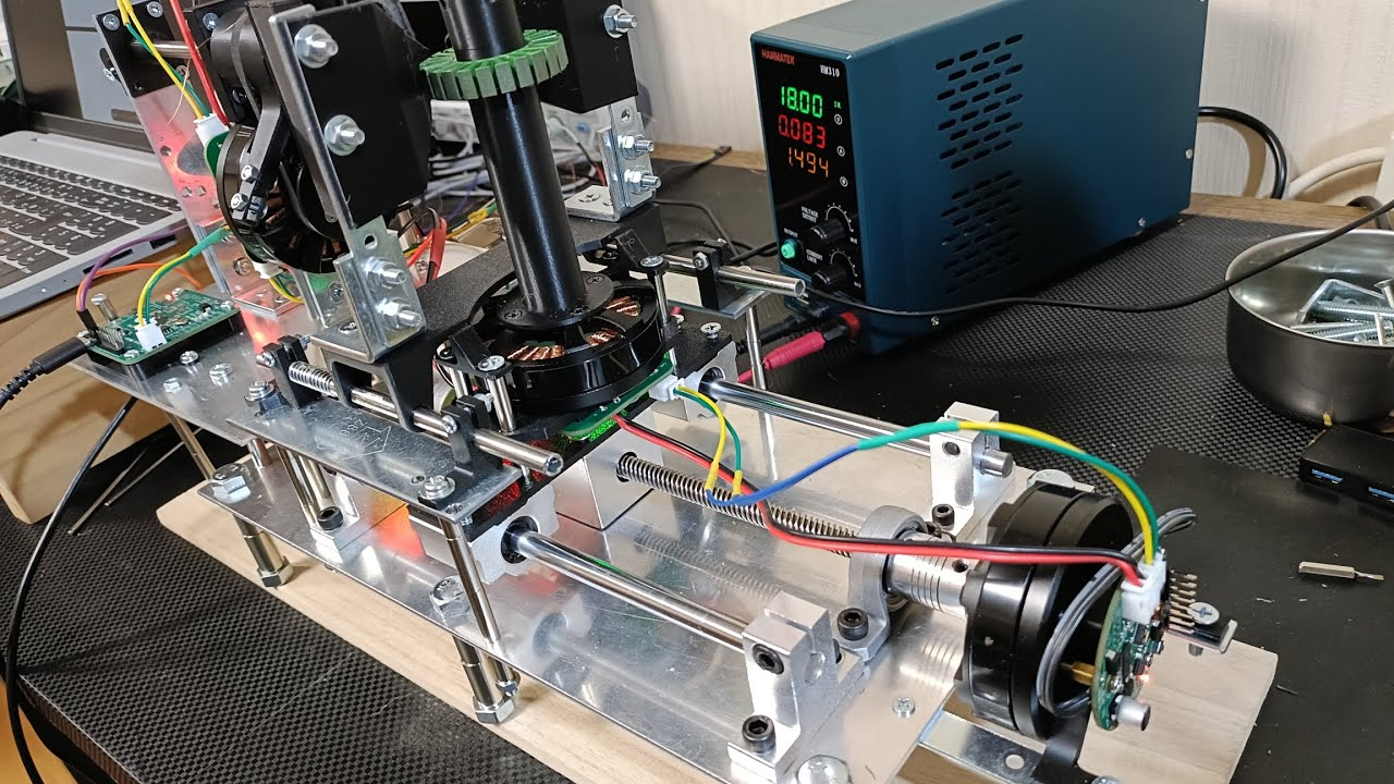
At the hobby level, this can be done with stepper motors, a microcontroller, a display, push buttons, 3D-printed fixtures, a lead screw, bearings, and a wire guide. At the professional level, machines add closed-loop servo systems, tension sensors, needle winding heads, programmable recipes, automatic cutting, varnishing, and quality inspection. Your first shop-built version does not need to look like it escaped from a factory floor. It just needs to be rigid, repeatable, and less moody than hand winding.
Understanding BLDC Motor Windings Before Building the Machine
Before designing the machine, it helps to understand what it is winding. Most small BLDC motors use three-phase stators. The stator has slots or teeth, and each phase is made from coils arranged around those teeth. Common layouts include concentrated windings, where each coil is wrapped around a single tooth or a small group of teeth, and distributed windings, where coils are spread across multiple slots.
Concentrated windings are common in compact outrunner motors, drones, electric skateboards, gimbals, and small robotics applications. They are simpler to wind, have shorter end turns, and can be suitable for small high-torque motors. Distributed windings can produce smoother magnetic fields and reduce certain harmonics, but they are harder to wind on small stators and usually require more complex tooling.
Star, Delta, Turns, and Wire Gauge
The winding configuration affects the finished motor. A star, or wye, termination often gives lower Kv and higher torque per amp compared with a delta termination using the same winding. Delta can produce higher Kv but may also increase circulating currents if the phases are not well matched. The number of turns per tooth also matters: more turns usually lowers Kv and raises resistance, while fewer turns usually raises Kv and lowers resistance. Wire gauge affects current capacity, slot fill, heat, and how much patience you will lose while trying to bend it around a tight stator tooth.
For example, a small 12-slot, 14-pole outrunner might use a concentrated three-phase winding pattern with alternating clockwise and counterclockwise coils. If each tooth needs 14 turns of 0.5 mm magnet wire, the machine must place those 14 turns consistently without scraping insulation, crossing too many layers, or pulling so hard that the wire stretches. The machine is not just counting loops; it is protecting electrical performance.
Main Components of a DIY BLDC Motor Winding Machine
A strong winding machine is more mechanical than magical. Electronics matter, but if the frame flexes, the wire guide wobbles, or the stator holder slips, even the smartest controller will produce disappointing coils. Think of the build as a small CNC machine with one very dramatic job: putting copper exactly where it belongs.
1. A Rigid Frame
The frame can be made from aluminum extrusion, steel plate, plywood, acrylic, or a mix of 3D-printed parts and metal rails. Aluminum extrusion is popular because it is straight, modular, and easy to adjust. Plywood can work for early prototypes, but it should be thick enough to resist vibration. A flexible frame creates uneven wire tension and poor layer control, so this is not the place to save three dollars and then spend three weekends troubleshooting.
2. Stator Holder or Mandrel
The stator holder must center the stator accurately and lock it in place. A simple design may use a shaft through the stator bore with spacers and nuts. A better version uses a custom 3D-printed or machined mandrel that matches the stator’s inner diameter. For outrunner stators, make sure the fixture allows access to each tooth and does not block the wire path.
3. Rotation or Indexing Axis
Many DIY machines use a stepper motor to rotate or index the stator. A common NEMA 17 stepper can work for small motors, while larger stators may need a NEMA 23 or a geared stepper. The machine should be able to move one tooth position at a time with repeatable accuracy. If the stator has 12 teeth, the controller needs to index 30 degrees per tooth. If it has 9 teeth, the indexing step is 40 degrees. The math is simple; the backlash is where the comedy begins.
4. Winding Arm or Needle
There are two common approaches. In a rotating-arm machine, the wire guide moves around a fixed stator tooth. In a needle winder, a narrow tube or needle passes wire around the tooth while the stator is indexed between coils. Needle-style winding is often better for tight BLDC stators because it can reach into narrow spaces, but it is mechanically more demanding.
5. Wire Tension System
Good wire tension keeps coils tight and repeatable. Too little tension makes loose, uneven windings. Too much tension can stretch wire, damage enamel insulation, or pull the stator out of alignment. A basic tensioner can use felt pads, spring-loaded rollers, or a small adjustable brake on the spool. More advanced designs use load cells, dancer arms, or closed-loop torque control. For a home build, a smooth adjustable tensioner is usually enough to start.
6. Traverse or Wire Guide
If the winding method requires the wire to move side to side, a lead screw and linear rail can guide it. This is similar to the traverse mechanism used in many coil-winding machines. The guide movement should be synchronized with the rotation so the wire lays evenly across the tooth or bobbin width. A simple lead screw driven by a stepper motor can provide precise movement, especially when paired with a clean rail and minimal backlash.
7. Controller and User Interface
An Arduino, ESP32, Raspberry Pi Pico, or similar microcontroller can control the machine. For a straightforward build, an Arduino with stepper drivers, push buttons, a rotary encoder, and an LCD display is enough. The menu can include turns per coil, winding speed, direction, stator slot count, wire guide pitch, and jog controls. More advanced builders may use GRBL-style motion control, a touchscreen interface, or a PC-based control panel.
Designing the Machine: Start Simple, Then Add Precision
The smartest way to build a BLDC motor winding machine is not to build the final version first. Build the awkward prototype. Let it expose the real problems. Then redesign the parts that caused the most trouble. This is the engineering equivalent of letting the machine roast you politely before you commit to nicer materials.
Prototype Layout
A useful starter layout includes a horizontal stator shaft, a stepper-driven indexing plate, a wire spool mounted behind the machine, an adjustable tensioner, and a hand-guided or stepper-guided wire nozzle. The first version can even be semi-automatic: the machine counts turns and rotates the stator, while the operator guides the wire by hand. That may sound less exciting than full automation, but it teaches exactly what the wire wants to do when it meets tight corners, sharp laminations, and human optimism.
Choosing Motion Hardware
Stepper motors are popular because they are inexpensive, easy to control, and accurate enough for many winding tasks. A typical 1.8-degree stepper has 200 full steps per revolution, and microstepping can make motion smoother. However, microstepping does not magically create unlimited torque or perfect accuracy. Use proper current settings, stable drivers, and enough mechanical reduction if the axis needs holding strength.
BLDC motors with encoders can also be used for winding machines, especially when closed-loop angle control or torque control is desired. This can be elegant for wire tension and smooth motion, but it adds complexity. For most first builds, steppers are easier. For a polished second or third version, closed-loop BLDC control becomes attractive, especially if the machine needs fast, quiet, repeatable operation.
How to Plan the Winding Process
The winding machine is only as good as the winding recipe. Before pressing start, define the stator geometry, winding pattern, turns per tooth, phase order, direction, wire diameter, target termination, and acceptable resistance balance between phases.
Create a Winding Map
A winding map tells the machine and the operator which tooth gets which phase and which direction. For example, a 12-slot stator might follow a repeating A-B-C phase pattern, with some teeth wound clockwise and others counterclockwise depending on the motor design. Marking the stator with small labels during testing helps prevent confusion. Copper wire does not care about your memory, and it will happily let you make the same mistake six times.
Set Turns and Speed
Start slowly. A machine that winds beautifully at 40 RPM may become a wire-flinging carnival ride at 140 RPM. Set a conservative speed, confirm the wire path, then increase only after the coils are stacking correctly. Turns should be counted by the controller, but visual verification is still useful during the first few coils. Hall sensors, optical interrupters, encoders, or step counts can all be used, depending on the machine design.
Protect the Wire Insulation
Magnet wire is coated with thin enamel insulation. If the machine scrapes it against sharp stator edges, the motor may short between turns or phases. Smooth every guide surface that touches wire. Use ceramic eyelets, polished brass tubes, PTFE guides, or printed guides with carefully sanded surfaces. Add slot liners or insulation paper when needed. A winding machine should guide wire like a careful tailor, not like a cheese grater with ambition.
Testing the Finished Winding
After winding, do not immediately connect the motor to a controller and hope for fireworks-free success. Test first. Measure phase-to-phase resistance and compare all three readings. They should be very close. Use a continuity tester to check that windings are not shorted to the stator core. Inspect the coils for damaged enamel, loose loops, or wires crossing where they should not.
After the electrical checks, secure the windings. Many motor builders use motor-safe varnish or epoxy designed for electrical insulation and heat resistance. This reduces vibration, improves heat transfer, and helps the windings survive real operation. Avoid adhesives that become brittle, attack enamel insulation, or soften badly with heat.
First Spin Test
For the first spin, use a current-limited power supply or a controller configured conservatively. Start at low voltage and low current. Listen for roughness, clicking, cogging beyond normal expectations, or abnormal heat. A properly wound BLDC motor should spin smoothly, with balanced phases and predictable behavior. If it stutters, overheats, or draws too much current with no load, stop and inspect before blaming the controller. Sometimes the controller is innocent. Sometimes.
Common Mistakes When Making a BLDC Motor Winding Machine
The most common mistake is underestimating wire handling. The electronics may work perfectly, but if the wire path has friction, sharp bends, inconsistent tension, or poor spool control, the machine will produce messy coils. The second mistake is assuming all stators can be wound with the same tool head. A large open stator and a tiny drone motor stator are completely different animals.
Another mistake is ignoring backlash. If the indexing axis has play, each coil may start at a slightly different position. That affects neatness and repeatability. Use proper bearings, tight couplers, and mechanical stops where helpful. Also avoid designing the machine so that wire tension pulls directly against a weak printed part. 3D printing is wonderful, but even the best printed bracket can develop a sudden interest in becoming two brackets.
Finally, do not skip documentation. Record wire size, turns, phase pattern, termination, stator dimensions, winding direction, resistance readings, and test results. The first successful motor is exciting. The second successful motor happens because you wrote down what worked.
Practical Build Example: A Small Desktop BLDC Stator Winder
A practical desktop design might use a 2040 aluminum extrusion frame, a NEMA 17 stepper for stator indexing, a second stepper for a wire guide lead screw, an Arduino Nano or ESP32 controller, two stepper drivers, a 16×2 LCD, a rotary encoder, and an adjustable felt-pad tensioner. The stator mounts on a removable mandrel. The wire spool sits on a low-friction shaft behind the machine, with a light brake to prevent overrun.
The control menu allows the operator to set the slot count, turns per tooth, winding direction, guide travel, speed, and number of repeated coils. During operation, the machine rotates the winding axis or helps index the stator after each coil. A foot switch can be useful because it lets the operator pause instantly while keeping both hands near the wire path. A clear guard around rotating parts is also wise, because spinning copper wire has no respect for your knuckles.
This kind of machine is not a replacement for an industrial stator production line, but it can dramatically improve consistency for prototypes, rewinds, small robotics motors, educational labs, and experimental BLDC designs. It also makes the winding process easier to study. Once you can control speed, tension, turns, and indexing, you can compare winding patterns and see how design choices affect motor behavior.
Safety and Reliability Tips
Keep fingers, loose sleeves, long hair, and dangling wires away from rotating parts. Add an emergency stop button within easy reach. Use a fused power supply and keep motor driver wiring tidy. Do not operate the machine with exposed high-current connections. If using varnish, epoxy, soldering tools, or heat guns, work in a ventilated area and follow product instructions.
Mechanically, add guards where the wire could whip or snag. Electrically, use strain relief on cables and avoid routing signal wires beside noisy motor power wires unless necessary. Software should include soft limits, pause controls, and a way to recover after a stopped job. A machine that can resume from turn 126 is much friendlier than one that forces you to start over because someone sneezed near the power switch.
Experiences From Making A Brushless DC Motor Winding Machine
The first real lesson from making a brushless DC motor winding machine is that winding is not one problem. It is ten small problems wearing the same copper-colored jacket. At first, most builders focus on the glamorous parts: the stepper motors, the controller, the display, maybe even a neat enclosure with buttons that make the machine look like it belongs in a miniature factory. Then the wire arrives, and the wire has opinions.
In practice, wire tension becomes the heart of the build. A simple spool holder may work for five turns, then suddenly the spool over-spins and throws a loose loop. A tight brake may solve that problem, only to create another one by making the wire drag unevenly. The best experience is to treat tension as adjustable, visible, and testable. A spring-loaded arm or dancer pulley helps reveal what the wire is doing. If the arm bounces wildly, the feed path is not smooth. If the wire sings like a tiny guitar string, the tension is probably too high.
The second lesson is that stator holding matters more than expected. A small amount of wobble at the mandrel becomes a large annoyance at the tooth. A good fixture should center the stator, resist rotation, and allow quick removal. For prototype work, several interchangeable mandrels are better than one universal holder that almost fits everything. “Almost” is where accuracy goes to retire.
The third lesson is to slow down during early tests. Fast winding looks impressive on video, but slow winding teaches more. At low speed, you can see whether the wire is stacking, slipping, scraping, or climbing over previous turns. Once the pattern works slowly, speed can be increased. Trying to tune the machine at high speed is like learning to park by entering a demolition derby.
The fourth lesson is that software should be boring, clear, and forgiving. A simple menu with turns, speed, direction, slot index, and pause is more useful than a complicated interface that hides basic settings. Add manual jog controls for every axis. Add a reset function that does not erase the entire job by accident. Add a turn counter that can be corrected manually, because real workshops have interruptions, and interruptions enjoy arriving at turn 73 of 86.
The fifth lesson is to document every winding test. Write down the wire diameter, number of turns, winding direction, phase sequence, resistance readings, and first spin behavior. Photos are useful, especially close-ups of the first and last turns on each tooth. When a motor runs well, documentation turns success into a repeatable recipe. When it runs badly, documentation turns failure into useful evidence instead of a mysterious copper sculpture.
Finally, expect the machine to evolve. The first version may be semi-automatic. The second may add a better guide. The third may add closed-loop tension or a cleaner indexing fixture. That is normal. A BLDC motor winding machine is not just a tool; it is a teacher. It teaches mechanics, electronics, motor theory, patience, and the ancient workshop truth that every “quick improvement” requires at least two more screws than you currently own.
Conclusion
Making a brushless DC motor winding machine is a rewarding project because it combines motion control, motor theory, mechanical design, electronics, and hands-on craftsmanship. The machine does not need to be industrial-grade to be useful. Even a modest desktop winder can improve coil consistency, reduce manual fatigue, and make BLDC motor experiments far more repeatable.
The best approach is to start with a rigid frame, a reliable stator holder, controlled wire tension, accurate turn counting, and simple software. Once those basics are solid, advanced features such as automated indexing, programmable winding patterns, closed-loop tension, and improved wire guides can be added. In the end, the goal is not just to wrap copper around steel. The goal is to build a machine that makes each winding predictable, testable, and good enough that your finished motor does not immediately file a complaint.